LKSS-DAUGHTER-BOARD
LKSS-DAUGHTER-BOARD is an accessory board compatible with the FRDM-IMX93 board, designed to be used in the context of Linux Kernel Summer School and offering the following hardware features:
40-pin expansion header and socket
4 x push button
1 x power LED
3 x user-controllable LEDs
1 x 4-pin header compatible with BMP280-based module
1 x 7-pin header compatible with ST7789V-based LCD module
A top view of the accessory board is shown in Figure 13.
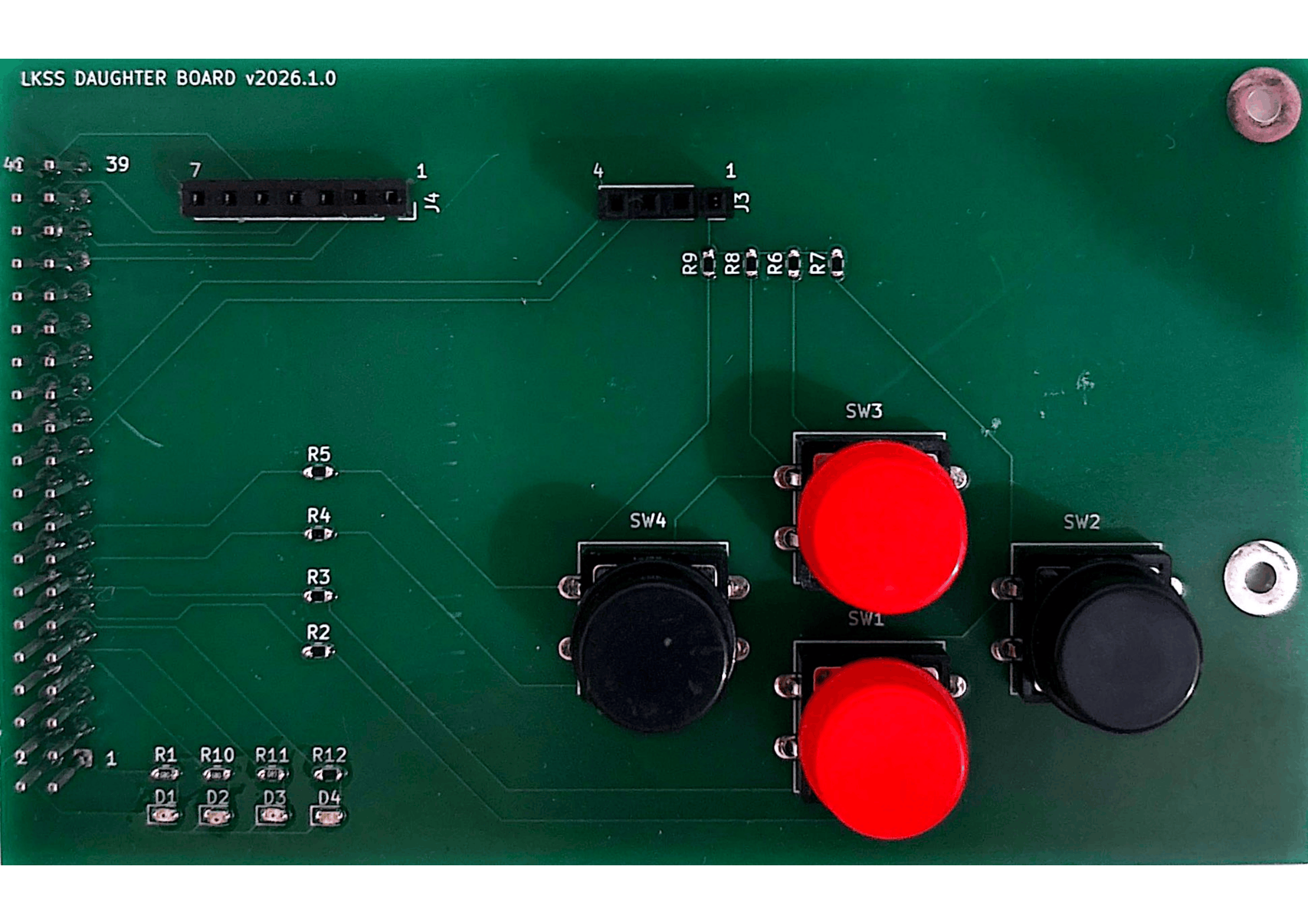
Figure 13 Top view of the LKSS-DAUGHTER-BOARD board
Connecting the modules
The accessory board contains two pin headers (J3 and J4), which can be used to connect the BMP280 and ST7789V-based modules. The two modules should be connected as shown in Figure 14.
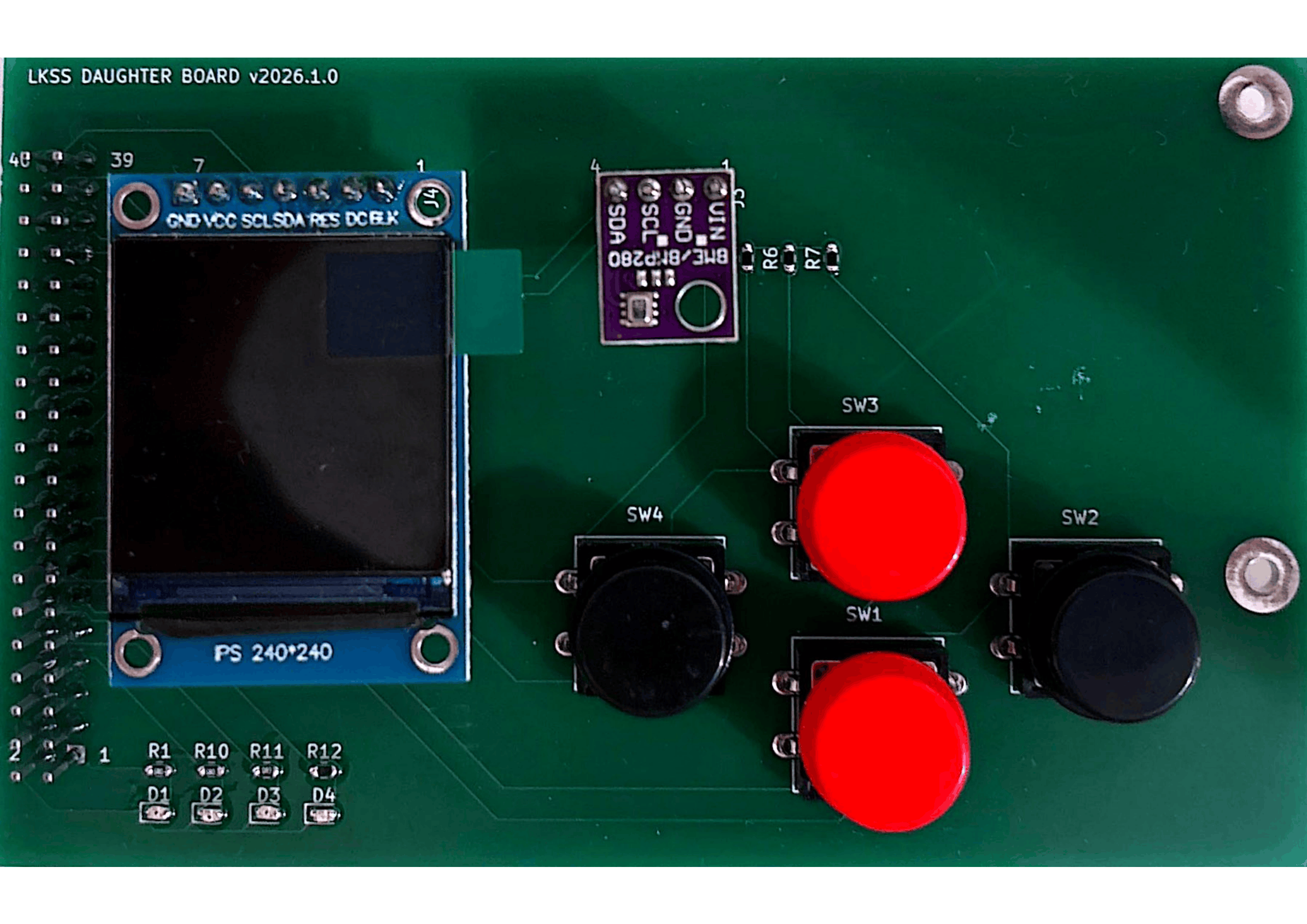
Figure 14 Connecting the sensor and LCD modules
Connecting the accessory board
The accessory board should be connected to the FRDM-IMX93 board using the 40-pin expansion header. To do so, make sure pin 1 of both expansion headers are aligned and then slowly push the accessory board’s socket in.
Warning
Make sure FRDM-IMX93’s power source is disconnected while doing this!
Figure 15 shows the two connected boards.
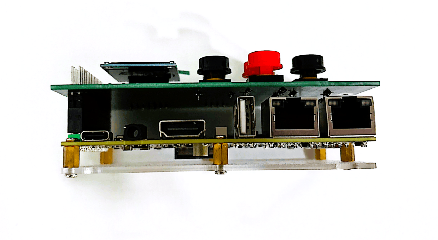
Figure 15 FRDM-IMX93 and accessory board connection
To check if the accessory board was properly connected, connect the power supply to the FRDM-IMX93 board. If everything went well, the power LED on the accessory board (i.e. D1) should be turned on as shown in Figure 16.
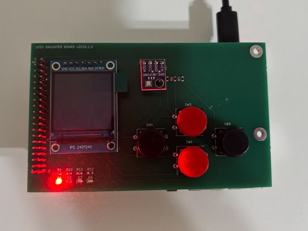
Figure 16 Accessory board power LED
Design files
The archive containing the design files can be downloaded from
here. This includes:
.
├── BOM.csv       # bill of materials
└── SCHEMATIC.pdf # board schematic