Booting the FRDM-IMX93 board
This page describes the steps required for booting the Linux kernel on the FRDM-IMX93 board.
Prerequisites
Before proceeding, make sure you prepare your development environment by following the steps described here. Additionally, please make sure you also read this page to get acquainted with the FRDM-IMX93 board.
Hardware setup
As described here, the board has three USB-C ports, which we’ll need to connect to our host computer in order to boot and debug the board.
Configuring the boot switch
We will be using USB as the boot medium. As such, please make sure that the boot switch is set to 1000 as described here.
Connecting DEBUG USB
First, connect the DEBUG USB port to your computer as shown in Figure 8.
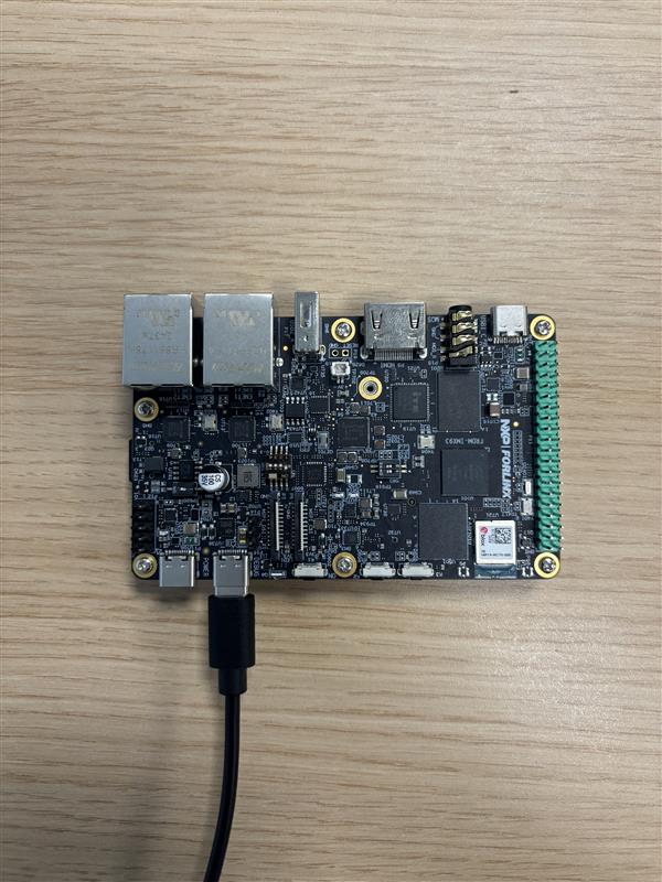
Figure 8 FRDM-IMX93 DEBUG USB connection
To make sure the connection was successful, you can:
Run sudo dmesg in your terminal. Look for the following logs
(or something similar):

If the board was detected, you should see two new ttyACM devices.
Open up Device Manager:
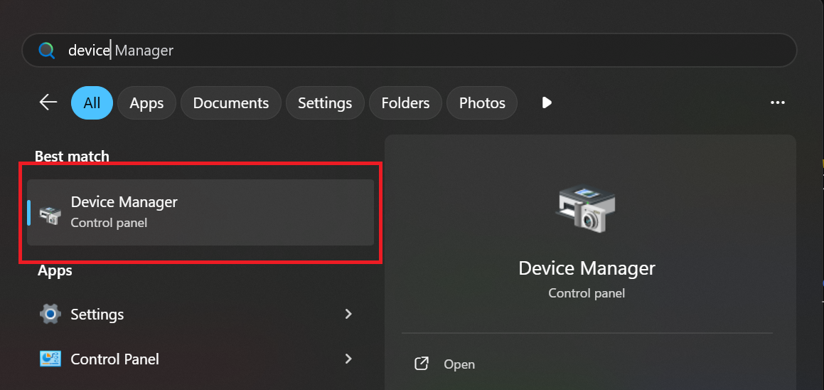
Look for and open the Ports (COM & LPT) tab:

If the board was detected, you should see two new CH342 serial devices.
Connecting POWER USB
Now, connect the POWER USB to a power source [1] as shown in Figure 9.
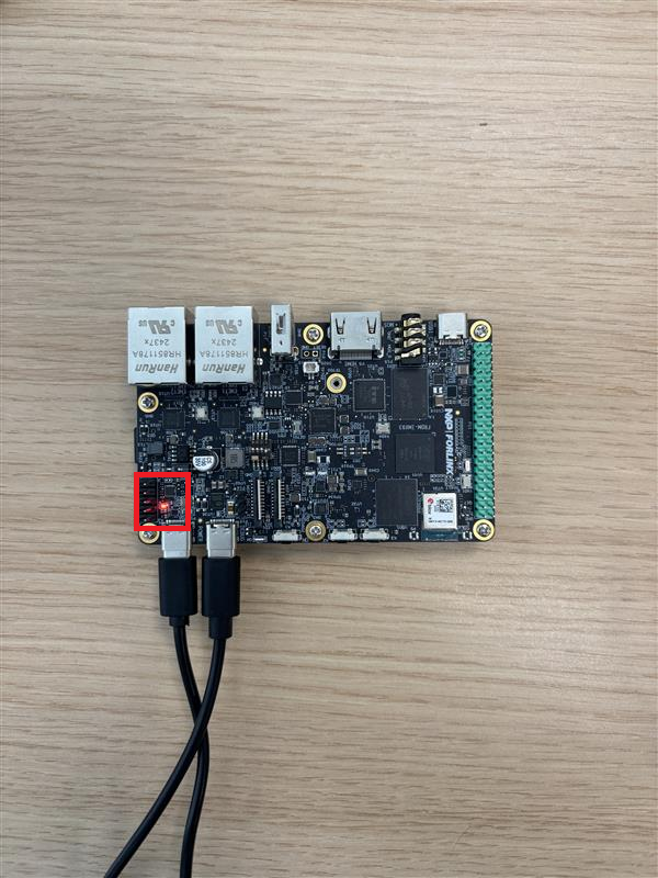
Figure 9 FRDM-IMX93 POWER USB connection
The red LED highlighted in Figure 9 indicates that the board is connected to a power source.
Connecting BOOT USB
Finally, connect the BOOT USB as shown in Figure 10.
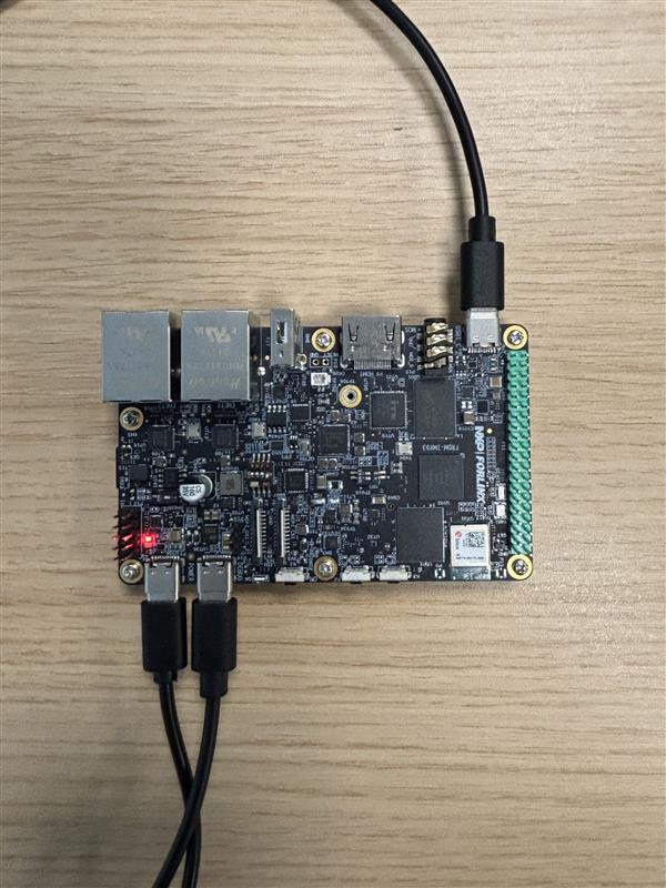
Figure 10 FRDM-IMX93 BOOT USB connection
To make sure the connection was successful, you can:
Run sudo dmesg in your terminal. Look for the following logs
(or something similar):

The manufacturer name, idVendor, and idProduct should match those shown above.
Open up Device Manager:
Look for and open the Human Interface Devices tab:
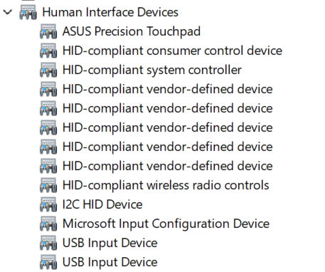
You should see that a new USB Input Device was added. To check if the new entry was added as a result of connecting the board:
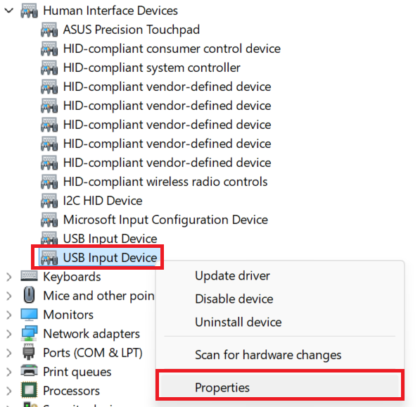
Open the Properties tab by right-clicking on the device:
Go to the Details tab and select the Hardware Ids property:
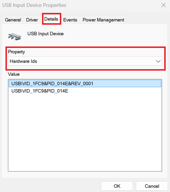
The device should have VID 1FC9 and PID 014E.
Software setup
Preparing the kernel image
To boot the Linux kernel, we’ll first have to compile it. To do so, run:
./scripts/lkss.py compile -j$(nproc) --install-modules --clean-config
Note
If this is not your first kernel compilation, you can omit the –clean-config flag.
Note
The compilation might take a while, depending on your host’s processing power.
If the compilation was successful, you should now see the output directory, containing the following build artifacts:
output/
├── Image # compiled Linux kernel image
└── imx93-11x11-frdm.dtb # board DTB
Serial console setup
For debug purposes, the interaction between the host computer and the board is performed using the DEBUG USB port. From the software’s point of view, this interaction requires opening up a serial console on your host computer. To do so:
Open a minicom [2] console:
sudo minicom -D /dev/ttyACM0
Open the help menu by pressing CTRL-a Z:
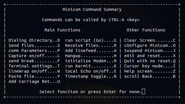
Open the cOnfigure Minicom menu by pressing O (capital letter):
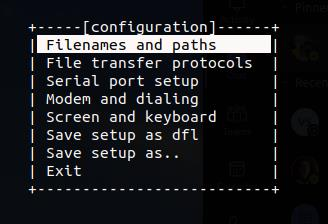
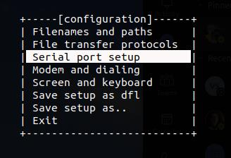
Open the Serial port setup menu by using the arrow and Enter keys:
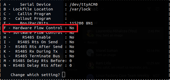
Make sure Hardware Flow Control is set to No:
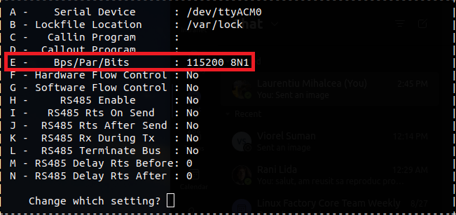
Make sure Bps/Par/Bits is set to 115200 8N1:
Close the Serial port setup menu by pressing Enter
Navigate to Save setup as dfl and press Enter
Navigate to Exit and press Enter
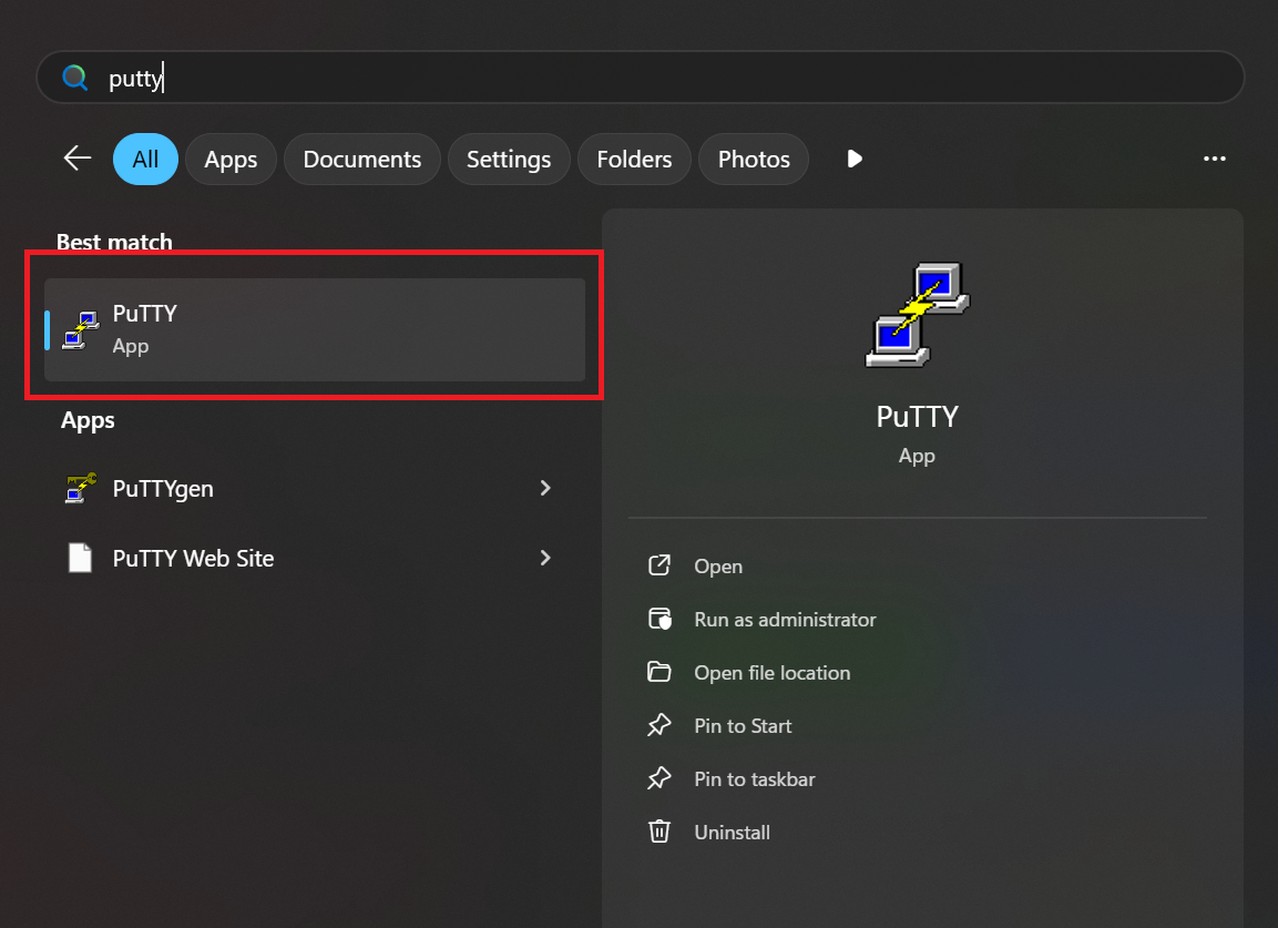
Open PuTTY:
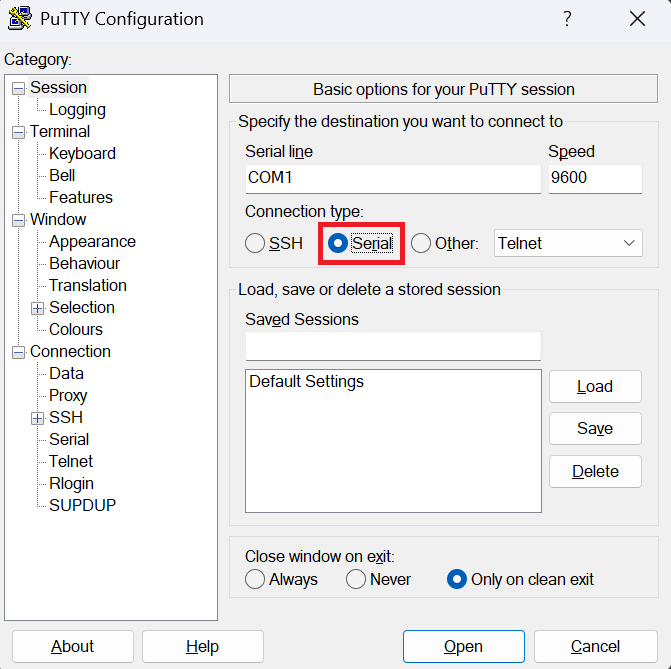
Select the Serial connection type:
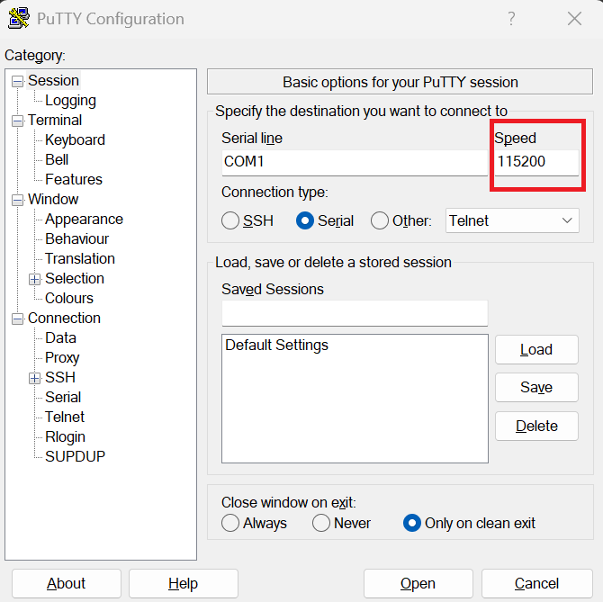
Set the speed to 115200:
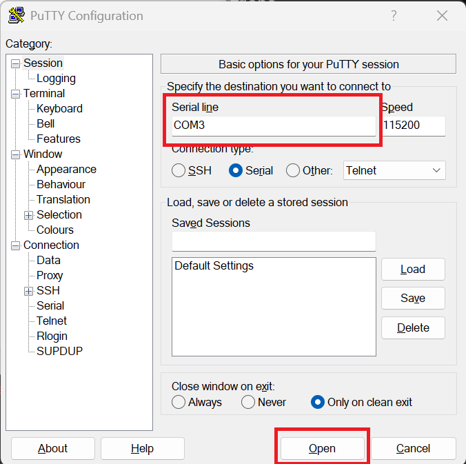
Enter COM3 as the serial device name and then click Open:
Note
The name of your serial device might differ. If so, open Device Manager as shown in Connecting DEBUG USB, navigate to the Ports (COM & LPT) tab and look for the name of your serial device.
Booting the board
To boot the board, run:
./scripts/lkss.py boot
If the command was successful, you should see the following output in your terminal:
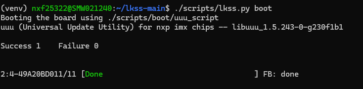
Additionally, based on your operating system, you should see some logs in your serial console as shown in Figure 11 or Figure 12.
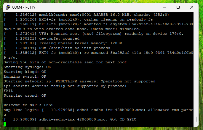
Figure 11 Logs printed during the board boot process (Windows, PuTTY)
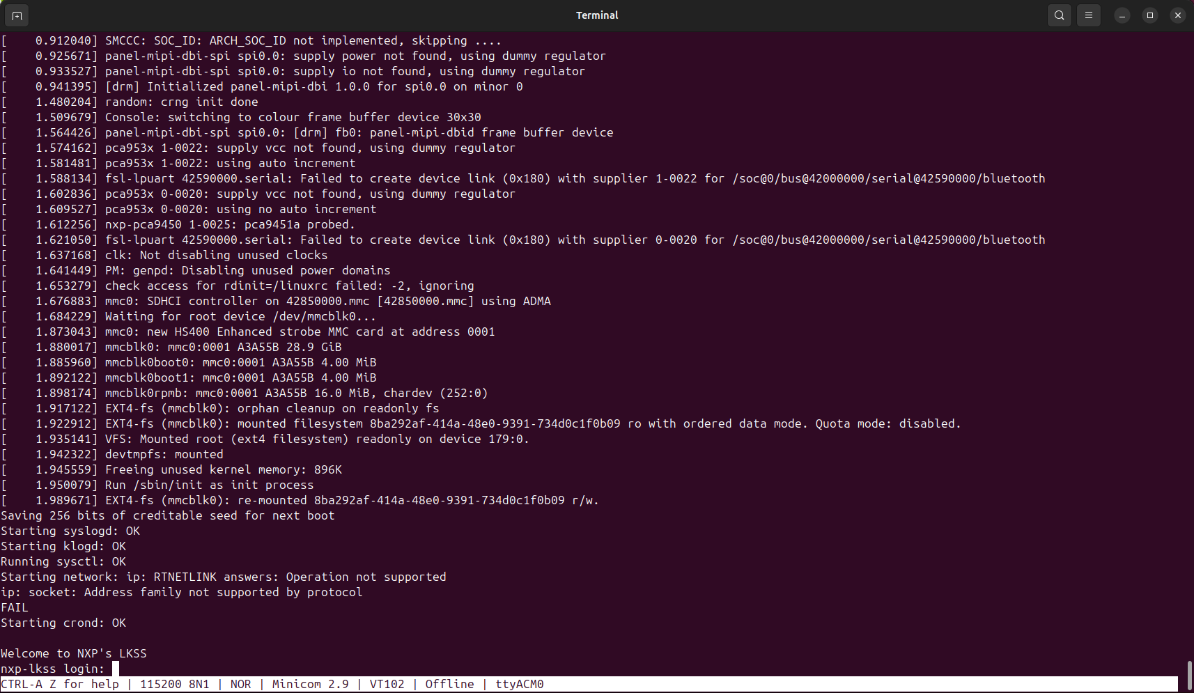
Figure 12 Logs printed during the board boot process (Linux, minicom)
Tip
If your serial console is not displaying any logs, try using the other serial device. For Linux, that would be ttyACM1 and for Windows, that would be COM4.
Footnotes