FRDM-IMX93
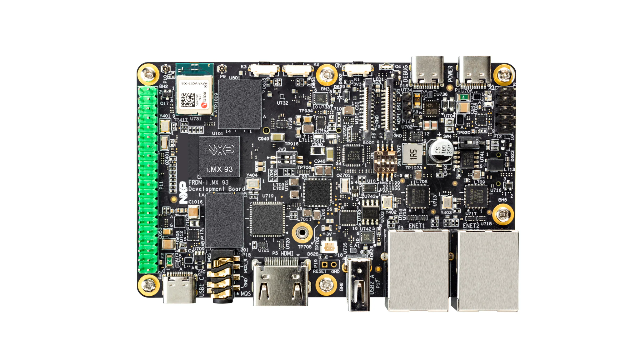
FRDM-IMX93 is a small and compact board developed by NXP, which integrates the i.MX93 chip and offers the following hardware features [1]:
2 x ARM Cortex-A55
1 x ARM Cortex-M33
3 x USB-C
32GB eMMC
2GB of RAM
40-pin expansion header
A top view of the board is shown in Figure 1.
The USB-C ports
As previously mentioned, the development board is equiped with three USB-C ports, which are highlighted in Figure 2.
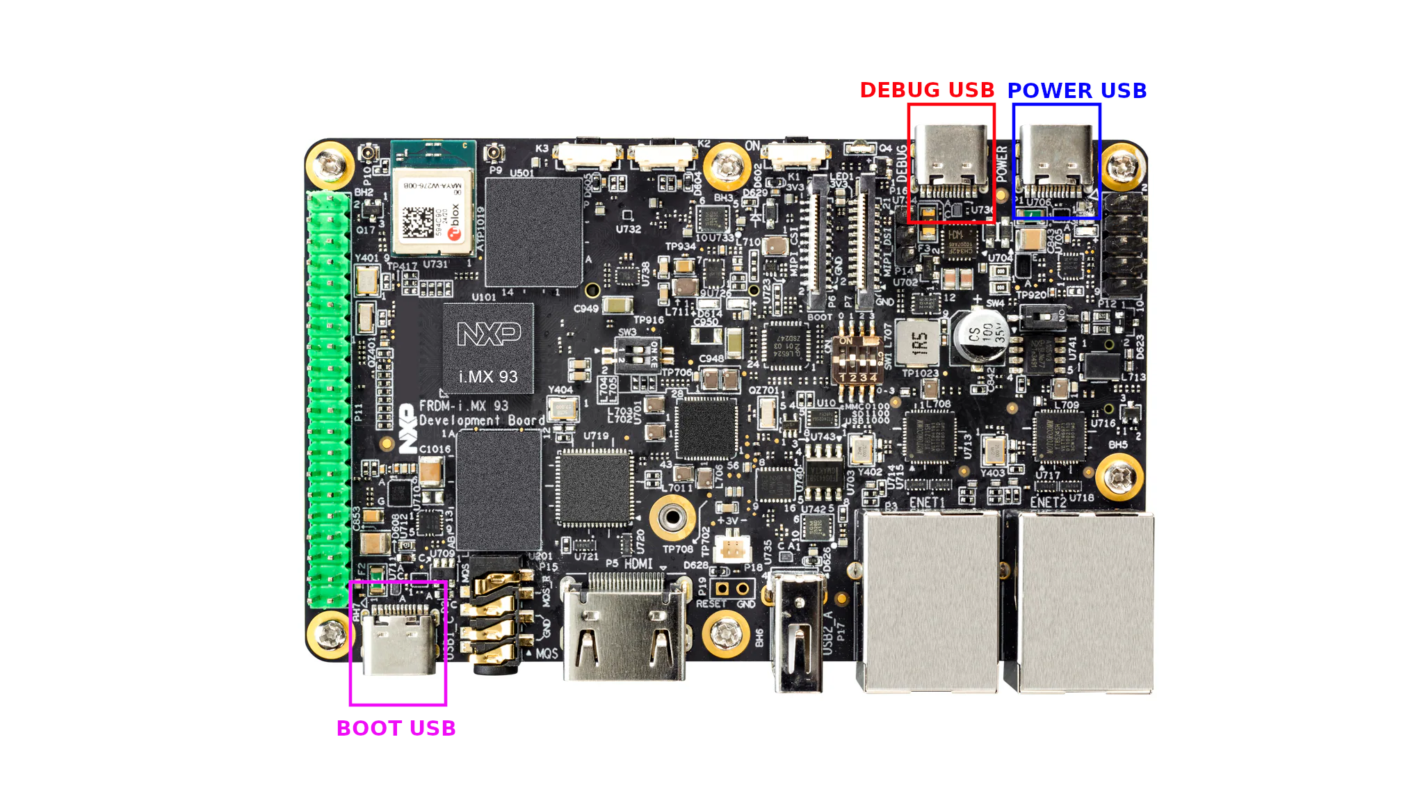
Figure 2 FRDM-IMX93 USB-C ports
Each of the three USB-C ports serves a different purpose, as described below:
BOOT USB: used to load the images required during the board’s boot process.
POWER USB: used to supply power to the board.
DEBUG USB: used for debugging and communicating with the bootloader [3].
The boot switch
Since the board supports multiple boot mediums, users will have to inform the boot ROM [4] where to get the bootloader image from. To do so, the board provides a series of mechanical switches, which shall be collectively known as the boot switch. Its location is highlighted in Figure 3 using yellow.
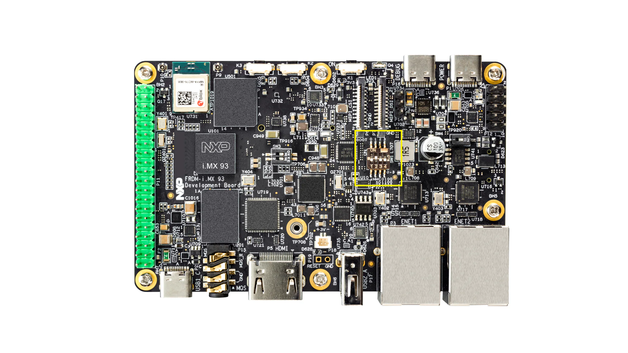
Figure 3 FRDM-IMX93 boot switch location
The boot switch consists of four switches, numbered from 1 to 4, each with two possible states: ON or OFF. The boot medium is chosen by placing these switches into the appropriate states.
The state of the boot switch can be encoded using a group of 4 bits, indexed from 1 to 4 (leftmost being index 1 and rightmost being index 4). Using this encoding, a value of 0/1 for bit i would correspond to switch i being OFF/ON. With this in mind, Table 2 provides the set of supported boot mediums and the corresponding state of the boot switch.
Boot switch state |
Boot medium |
|---|---|
1000 |
USB |
1100 |
SD |
0100 |
eMMC |
For example, if one wishes to boot the board over USB [5], according to Table 2, one would have to set switch 1 to ON, switch 2 to OFF, switch 3 to OFF, and switch 4 to OFF.
The expansion header
To allow communication with external modules, the board is equipped with a pin header made up of 40 pins. This is referred to as the expansion header and is highlighted in Figure 4.
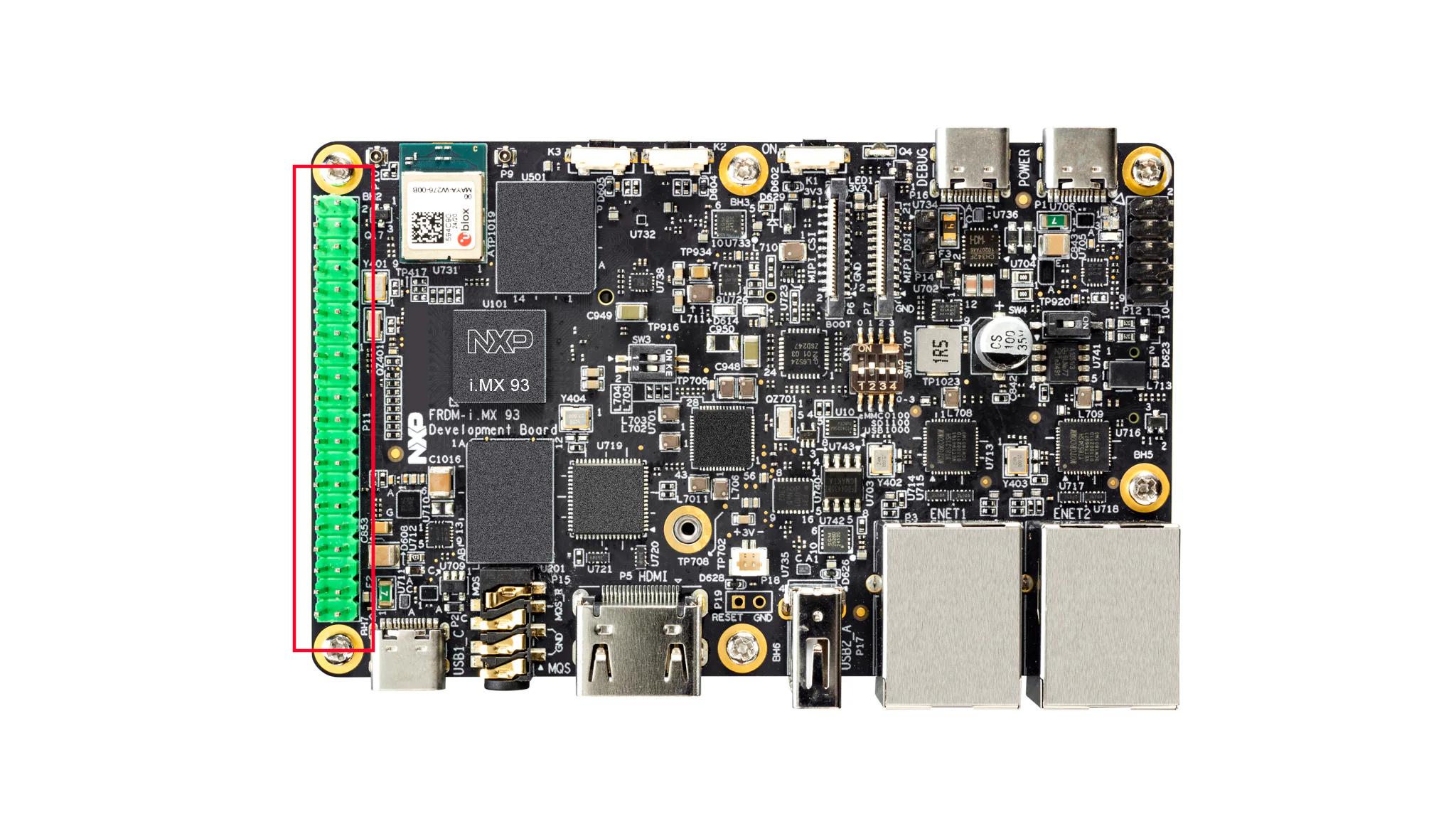
Figure 4 FRDM-IMX93 expansion header
Figure 5 showcases the schematic of the expansion header.
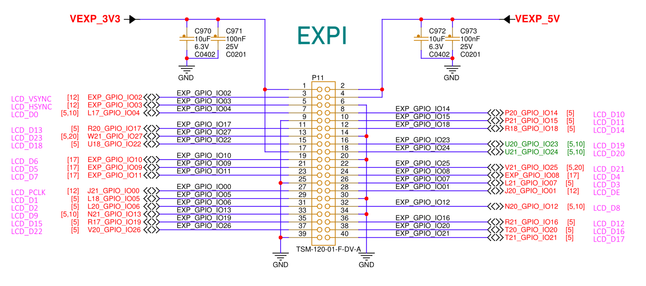
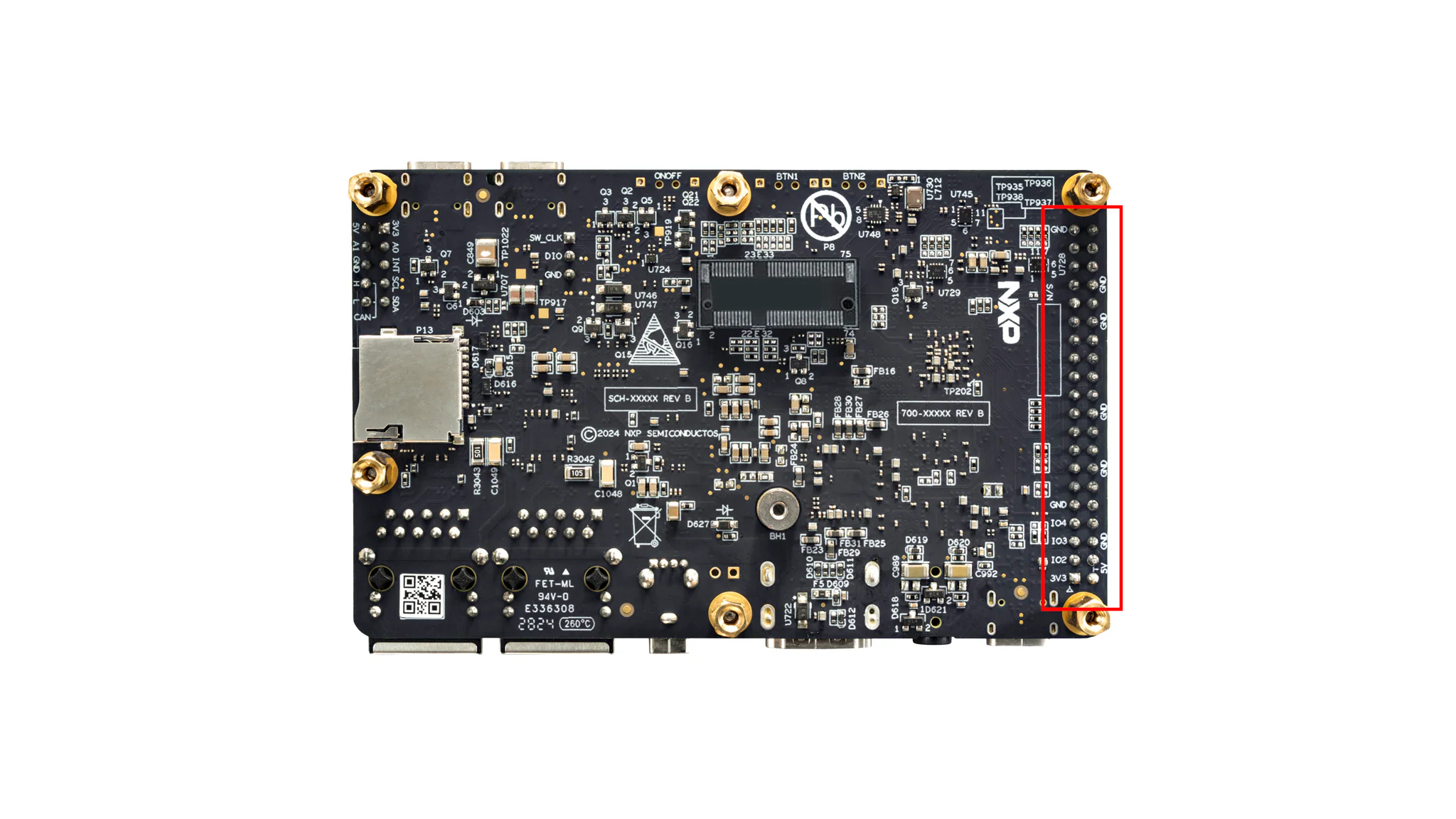
Looking at Figure 5, the pins of the expansion header are numbered from 1 to 40. To find the index of a pin on the physical board, first flip the board upside down and then look for the bottom part of the expansion header. This is highlighted in Figure 6.
After locating the expansion header, look for the 3V3 label inscribed near the soldered pins. According to Figure 5, this corresponds to pin 1 [8]. Its location is shown in Figure 7.
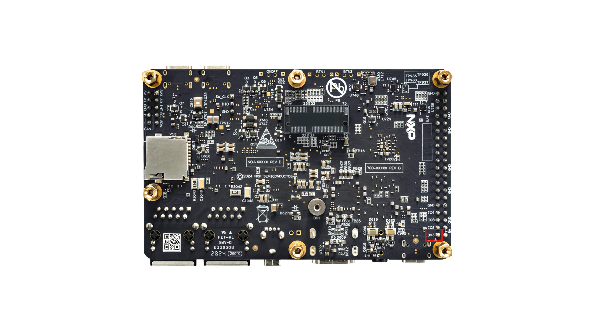
Figure 7 FRDM-IMX93 expansion header pin 1 location (bottom view)
The rest of the pins can be discovered based on the location of pin 1.
Useful resources
Footnotes