I2C Bus and the BMP280 Sensor Driver
Slides: here
Theory
I2C Protocol Fundamentals
So far (UART, GPIO) each wire carried data in a single direction. I2C
(Inter-Integrated Circuit) is different: many chips share the same two wires, and the
data line (SDA) is bidirectional, carrying bytes in both directions at different
points in a transfer. Sharing one bus instead of a dedicated link per chip is why almost
every sensor, EEPROM (Electrically Erasable Programmable Read-Only Memory), RTC (Real Time
Clock) and power-management chip on a board uses I2C.
The two wires
SCL– Serial CLock. Driven by the controller (formerly called the master) — the device that starts a transfer and provides the clock (here, the i.MX93). Every bit is sampled on a clock edge.SDA– Serial DAta. Used to transmit data, one bit at a time.
Devices on the bus must use open-drain (or open-collector) outputs so they can perform the wired-AND function. Such an output can only pull the line low; it can never drive it high. To make a line go high, the bus relies on external pull-up resistors (commonly around 4.7 kΩ) that pull the idle line up to the supply voltage (here, 3.3 V).
Why go through this trouble instead of normal push-pull outputs? Three reasons:
No short circuits. If two devices talk at once, the worst that happens is that the line is pulled low by one of them. With push-pull outputs, one chip driving high while another drives low would lead to a short circuit.
Wired-AND logic. Because anyone can pull the line low but the pull-up alone makes it high, the bus level is the logical AND of all participants. The line is high only if every device lets go of it. This single property is the foundation of acknowledgement, arbitration and clock stretching below.
Multi-controller and many targets on the same two pins. A target (formerly called a slave) is a device the controller talks to; targets are distinguished by address, not by extra wires.
Addresses
Each device on the bus has a unique 7-bit address (0x00–0x7F, so up to 128 devices in theory; some addresses are reserved, so fewer in practice). The address is baked into the chip; many chips let you change one or two low address bits by tying a select pin to GND or VDDIO — exactly what the BMP280’s SDO pin does above — so you can put two identical chips on one bus.
The BMP280’s address is selected by the SDO pin:
SDO tied to GND → address
0x76SDO tied to VDDIO → address
0x77
In this lab we wire SDO to GND, so the sensor lives at 0x76.
Anatomy of a transaction
Every transfer is framed by two special bus conditions that are only legal here:
START: SDA goes low while SCL is high. “I’m taking the bus.”
STOP: SDA goes high while SCL is high. “I’m done, bus is free.”
During normal data bits, SDA is only ever changed while SCL is low and is sampled while SCL is high; the high-SCL transitions are reserved for START/STOP precisely so they can’t be confused with data.
The waveform below shows three data bits. SDA settles to its value while SCL is low and
then holds steady through the SCL-high pulse, where the receiver samples it (‾ = high,
_ = low):
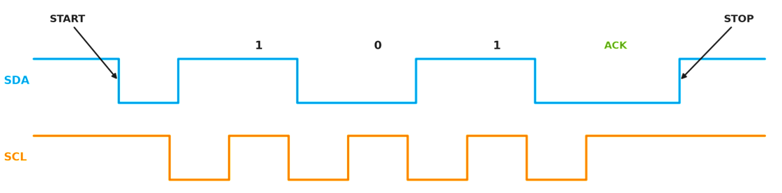
START and STOP break that rule on purpose: they are the only times SDA moves while SCL is high, which is exactly what makes them unambiguous frame markers:
A complete transaction looks like:
START → [7-bit address][R/W bit] → ACK → [data] → ACK → ... → STOP
After every 8 bits, the receiver pulls SDA low for one clock to acknowledge the byte (ACK); leaving the line high instead is a NACK, indicating the byte was not accepted or no further data is wanted. The controller uses a NACK on the last byte of a read to tell the target to stop sending.
Writing to a register
To write one byte to a register inside a chip, the controller sends:
START
device address + W (write) bit
the register address inside the chip (which internal byte we mean)
the data byte
STOP
Reading from a register
You cannot just “read register 0xD0” in one shot, because the chip has no idea which register you mean until you tell it. So a register read is really a write followed by a read:
START
device address + W → write the register address (this is the “dummy write”: no data, it just sets the chip’s internal pointer)
repeated START (a second START with no STOP in between — keeps the bus, switches direction)
device address + R (read) bit
read the data byte(s); the controller ACKs each byte except the last, which it NACKs
STOP
You don’t normally code this by hand — the kernel’s SMBus helpers (next section) do it for you — but understanding the shape explains why the API has separate “register” and “raw” calls.
Bus speeds
Standard mode: 100 kHz
Fast mode: 400 kHz ← what we use in this lab
Fast mode plus: 1 MHz
Speed is limited by the pull-up strength and bus capacitance: weaker pull-ups and long traces mean slower edges, which caps the usable clock.
Clock stretching
A slow target that isn’t ready can hold SCL low even though the controller released it. Thanks to wired-AND, the clock simply can’t rise until the target lets go, so the controller automatically waits. This is called clock stretching and it lets a fast controller talk to a slow device without any handshake protocol on top.
On the i.MX93
The i.MX93 implements I2C with the LPI2C (Low-Power I2C) controller — it has several
instances (LPI2C1…LPI2C8). Each one becomes a Linux i2c_adapter (a numbered bus
under /sys/bus/i2c/devices/). Exactly one of these LPI2C instances is routed to the
SCL/SDA pins on the EXT2 expansion header where you’ll wire the BMP280; figuring out
which one is your first lab exercise.
The Linux I2C Subsystem
Linux splits I2C into three layers so that a sensor driver never has to know how the SoC’s I2C hardware actually toggles wires:
+---------------------------+   your code (Day 4)
|  i2c_driver / i2c_client  |   "read register 0xD0 from the BMP280"
+---------------------------+
|        I2C core           |   generic transfer engine, SMBus emulation
+---------------------------+
|  i2c_adapter (controller) |   the LPI2C driver: actually drives SCL/SDA signals
+---------------------------+
          hardware bus
The controller (adapter) driver knows the LPI2C registers and produces real bus traffic. NXP already wrote this; you never touch it.
The I2C core is the glue. It matches devices to drivers, and crucially it can emulate the SMBus transactions (the write-then-read dance above) on top of the adapter’s raw transfer. That is why you can call one tidy function and get a correct register read.
Your device driver is an
i2c_driver. When a device that matches it appears on a bus, the core hands you ani2c_client— a handle representing that one chip at that one address — and calls yourprobe().
The three structures, in one breath: an i2c_adapter is a bus, an i2c_client
is a device on a bus, and an i2c_driver is the code that drives such devices.
SMBus vs. raw I2C. SMBus is a strict subset of I2C with defined transaction shapes
(read byte from register, write byte to register, block read, …). The i2c_smbus_*
helpers below are almost always what you want for a register-mapped sensor like the
BMP280, because they handle the dummy-write/repeated-START for you. The i2c_master_*
helpers give you raw byte-level control for the rare device that doesn’t fit the SMBus
pattern.
API |
Purpose |
|---|---|
|
Represents one I2C device; holds |
|
Read one byte from register |
|
Write one byte to register |
|
Burst-read |
|
Raw write of |
|
Raw read of |
Note
This lab uses the current I2C terminology — controller and target (the 2021
spec renamed the older master and slave). The Linux kernel API, however, still
carries the historical names: you will see i2c_master_send / i2c_master_recv
and the i2c_master_* family. They mean “controller-side”, so don’t let the spelling
confuse you.
Note
Every i2c_smbus_read_* call returns a signed value: a non-negative result is
your data, a negative result is a -errno error code. Always check for
``< 0`` before using the value — a disconnected SDA wire shows up here, not as a
crash.
Device Tree: I2C Nodes and Sensor Bindings
I2C devices cannot be auto-detected reliably (probing random addresses can upset other chips), so on an embedded SoC we declare them in the device tree. The controller appears as a node; each chip on the bus appears as a child of that controller node. The parent/child nesting is what tells the kernel “this BMP280 lives on this bus.”
Three properties do the heavy lifting:
reg— the device’s 7-bit I2C address (without the R/W bit). For the BMP280 with SDO->GND this is0x76.
Note
reg means “address on the parent bus”; on an I2C bus that’s the I2C address, on a memory-mapped bus it would be a base address.
clock-frequency— the SCL speed for the whole bus (400000= Fast mode).status—"okay"enables the node;"disabled"turns it off. SoC.dtsifiles ship most busesdisabled; the board.dtsflips on the ones it uses.
The #address-cells = <1> / #size-cells = <0> on the controller say “my children
are addressed by a single number and have no size” — i.e. an I2C address.
The pinctrl-0 / pinctrl-names properties hand the SCL/SDA pads to the controller;
the actual pad-to-function mapping lives in an iomuxc group.
&lpi2cX { /* Enable LPI2C7 (Exercise 1); add the bmp280 child in Exercise 3 */
#address-cells = <1>;
#size-cells = <0>;
clock-frequency = <400000>; /* Fast mode: 400 kHz */
pinctrl-0 = <&pinctrl_lpi2cX>;
pinctrl-names = "default";
status = "okay";
bmp280: pressure@76 {
compatible = "lkss,bmp280";
reg = <0x76>; /* I2C address: SDO tied to GND */
/* vddd-supply = <®_3v3>; optional regulator reference */
};
};
&iomuxc {
pinctrl_lpi2cX: lpi2cX-grp {
fsl,pins = <
/* Example i.MX93 entries — CONFIRM the pad names and the
* mux/config value against the i.MX93 Reference Manual IOMUX
* table and the FRDM-IMX93 schematic for the EXT2 header.
* Format: <PAD_MACRO config_value>
* Example (LPI2C7 on the GPIO_IO pads):
* MX93_PAD_GPIO_IO08__LPI2C7_SDA 0x40000b9e
* MX93_PAD_GPIO_IO09__LPI2C7_SCL 0x40000b9e
* The 0x...b9e value enables the internal pull-up and open-drain;
* I2C pads must be open-drain.
*/
>;
};
};
Note
compatible is the matchmaker. The string "lkss,bmp280" in the device tree
must appear verbatim in your driver’s of_match_table (Exercise 3) for the
kernel to bind your driver to this node. vendor,device is the naming convention;
we use the fake vendor lkss so we never collide with the real upstream
bosch,bmp280 binding.
The BMP280 Sensor
The BMP280 is a Bosch digital barometric pressure and temperature sensor in a tiny package. Internally it has an analog front-end that measures pressure and temperature, two ADCs that turn those into 20-bit raw numbers, and a register file you talk to over I2C (or SPI). It needs the temperature reading to correct the pressure reading, which is why we always read both.
For details check the datasheet
You interact with it entirely through its register map. Three groups matter:
Identity / control — who am I (
id), reset me (reset), how should I measure (ctrl_meas,config), am I busy (status).Calibration — 24 bytes of per-chip factory constants at
0x88. Every individual sensor is trimmed at the factory and stores its own coefficients; you must read them and feed them into the compensation maths.Raw output — the most recent 20-bit pressure and temperature ADC samples.
Register |
Address |
Purpose |
|---|---|---|
|
0xD0 |
Chip ID — always reads |
|
0xE0 |
Write |
|
0xF3 |
Bit 3: |
|
0xF4 |
Oversampling for temperature/pressure, power mode |
|
0xF5 |
Standby time, IIR filter coefficient, SPI 3-wire mode |
|
0xF7–0xF9 |
Raw 20-bit ADC pressure value |
|
0xFA–0xFC |
Raw 20-bit ADC temperature value |
|
0x88–0x9F |
24 bytes of factory calibration coefficients |
Note
The address range 0x88–0x9F is exactly 24 bytes (0x9F − 0x88 + 1 = 24).
That holds the 12 16-bit coefficients dig_T1..T3 and dig_P1..P9. The
BMP280’s bigger sibling, the BME280, adds humidity coefficients above 0x9F; on a
plain BMP280 there is nothing useful past 0x9F, so we read 24 bytes, not 26.
Power modes. The chip has sleep, normal (free-running) and forced modes. We use
forced mode: write ctrl_meas once, the chip takes a single measurement, then
drops back to sleep. This is the natural fit for “read a sensor on demand” and keeps
power use trivial.
Calibration and Compensation
The raw ADC values are not temperature or pressure. They are uncalibrated counts whose relationship to real physical units differs slightly from chip to chip because of manufacturing tolerances. To get usable numbers you combine the raw value with that chip’s own calibration coefficients using fixed formulas published by Bosch (datasheet section 3.11.3).
Bosch ships these as integer-only formulas so they run on MCUs with no FPU — which is
exactly why we can run them in kernel space, where floating point is forbidden. The
maths looks intimidating; you do not need to derive it, only to transcribe it
faithfully and respect the integer widths (s32 vs s64). One wrong shift or a
32 where a 64 was needed silently corrupts the result.
The 24 calibration bytes decode (little-endian) into:
dig_T1(u16),dig_T2(s16),dig_T3(s16)dig_P1(u16),dig_P2…dig_P9(s16each)
Temperature compensation — note the side effect: it computes t_fine, a
high-resolution intermediate that the pressure formula then consumes. Always run the
temperature compensation first.
/* All locals are s32 (signed 32-bit). adc_T is the raw 20-bit temperature.
 * Returns temperature in hundredths of a degree C (5123 == 51.23 degC),
 * and writes t_fine through the pointer for the pressure stage to use.   */
s32 bmp280_compensate_temp(struct bmp280_calib *c, s32 adc_T, s32 *t_fine)
{
    s32 var1, var2;

    var1 = ((((adc_T >> 3) - ((s32)c->dig_T1 << 1))) * ((s32)c->dig_T2)) >> 11;
    var2 = (((((adc_T >> 4) - (s32)c->dig_T1) *
              ((adc_T >> 4) - (s32)c->dig_T1)) >> 12) * (s32)c->dig_T3) >> 14;
    *t_fine = var1 + var2;
    return (*t_fine * 5 + 128) >> 8;   /* 0.01 degC units */
}
Pressure compensation — this is the full Bosch 64-bit integer formula. Intermediate
products overflow 32 bits, so every working variable is s64.
/* adc_P is the raw 20-bit pressure; t_fine comes from the temperature stage.
 * Returns pressure in Q24.8 fixed point: result / 256 == pressure in Pa.
 * Example: 24674867 -> 24674867 / 256 = 96386 Pa = 963.86 hPa.            */
u32 bmp280_compensate_press(struct bmp280_calib *c, s32 adc_P, s32 t_fine)
{
    s64 var1, var2, p;

    var1 = ((s64)t_fine) - 128000;
    var2 = var1 * var1 * (s64)c->dig_P6;
    var2 = var2 + ((var1 * (s64)c->dig_P5) << 17);
    var2 = var2 + (((s64)c->dig_P4) << 35);
    var1 = ((var1 * var1 * (s64)c->dig_P3) >> 8) +
           ((var1 * (s64)c->dig_P2) << 12);
    var1 = (((((s64)1) << 47) + var1)) * ((s64)c->dig_P1) >> 33;

    if (var1 == 0)
        return 0;       /* avoid divide-by-zero */

    p = 1048576 - adc_P;
    p = (((p << 31) - var2) * 3125) / var1;
    var1 = (((s64)c->dig_P9) * (p >> 13) * (p >> 13)) >> 25;
    var2 = (((s64)c->dig_P8) * p) >> 19;
    p = ((p + var1 + var2) >> 8) + (((s64)c->dig_P7) << 4);

    return (u32)p;       /* Q24.8 Pa */
}
To turn the Q24.8 result into hPa: pressure_Pa = p / 256, and
1 hPa = 100 Pa, so hPa = p / 25600. Keep the remainder if you want the two
decimal places (1013.25); see Exercise 6.
Sysfs Attributes
A driver’s job is only half done when it can read the sensor in probe; the user
needs the numbers too. The simplest way to publish a value to userspace is a sysfs
attribute — a virtual file under /sys that runs a callback in your driver each time
it is read.
The pieces:
DEVICE_ATTR_RO(name)declares a read-only attribute backed by a function you write calledname_show(). (There is alsoDEVICE_ATTR_RWfor writable ones.)The
showcallback has the signaturessize_t name_show(struct device *dev, struct device_attribute *attr, char *buf). You format your text intobufand return the number of bytes written, almost always viasysfs_emit(buf, "...").Multiple attributes are bundled into a
struct attribute_groupand registered in one go withsysfs_create_group(&client->dev.kobj, &grp)inprobe— and torn down withsysfs_remove_group()inremove.
Reading the file triggers a fresh measurement on demand, so the flow inside show
is: trigger forced-mode → wait → read raw → compensate → sysfs_emit the formatted
result. Each open/read is one measurement, which is exactly the on-demand behaviour we
want.
Introduction to the IIO Subsystem
Manually creating a temperature and a pressure sysfs file works, but every driver
author would invent their own file names, units and layout — and userspace tools would
have to special-case each one. The kernel solves this with IIO (Industrial I/O), the
standard framework for sensors that produce analog-ish data: ADCs, accelerometers,
gyros, light, pressure, temperature, and so on.
What IIO gives you for free:
A consistent layout at
/sys/bus/iio/devices/iio:deviceX/.Standard channel names with defined units, e.g.
in_pressure_input(kPa) andin_temp_input(milli-°C), plus*_raw/*_scaleconventions so a generic app can read any IIO sensor without knowing the chip.Buffered/triggered capture, timestamps, and tools like
iio_infoandlibiiothat work across all IIO devices.
The trade-off is abstraction: an IIO driver describes its sensor through
iio_chan_spec tables and read_raw callbacks rather than reading registers in
probe. That structure is great in production but it hides the very I2C mechanics this
lab is about.
So for Day 4 we deliberately write a plain sysfs driver: you see every register read
and every transaction with nothing in the way. The real upstream driver lives in
drivers/iio/pressure/bmp280-core.c (with the I2C glue in bmp280-i2c.c) and is
an IIO driver — read it after the lab to see how the same chip is handled “properly”.
Cheatsheet: I2C and BMP280 APIs
Function / Macro |
Purpose |
|---|---|
|
Read one byte from register |
|
Write one byte to register |
|
Burst-read |
|
Store driver private data pointer in the |
|
Retrieve driver private data pointer |
|
Read a little-endian 16-bit value from an unaligned byte pointer |
|
Format a sysfs |
|
Declare a read-only sysfs attribute; implement |
|
Register a group of sysfs attributes |
|
Allocate zeroed memory freed automatically when the device unbinds |
|
Register + unregister an |
Lab exercises
Note
Exercises for this lab can be found in drivers/lkss/lab4. You are given a
code skeleton (bmp280.c) with blocks marked TODO; each exercise tells
you which block to complete.
Prerequisites
Go over the cheatsheet here.
Make sure you connect the accessory board as described here. You can download its schematic from the Design files.
Make sure to enable CONFIG_LKSS_DRIVERS_LAB4 and the related configs in the menuconfig before compiling a new exercise.
1. Enable the I2C controller (easy)
Description
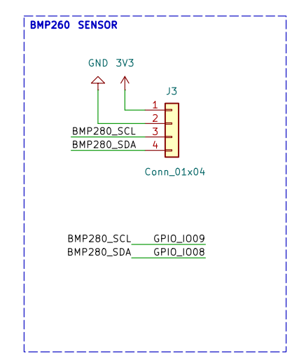
The schematic above shows that the BMP280 on the EXT2 header is wired to the LPI2C7 controller (pads
GPIO_IO08 = SDA, GPIO_IO09 = SCL - see arch/arm64/boot/dts/freescale/imx93-pinfunc.h). That controller ships disabled in the SoC
.dtsi (see arch/arm64/boot/dts/freescale/imx91_93_common.dtsi), so Linux has no bus for the sensor to live on and nothing can be scanned yet.
Your first job is to enable the controller — without adding the sensor itself.
Steps
Open the FRDM board DTS file
arch/arm64/boot/dts/freescale/imx93-11x11-frdm.dts.Add an
&lpi2c7override: setstatus = "okay", the bus speed and a pinctrl group. Do not redefine the controller —reg,clocks,interruptsanddmasalready live in the.dtsi; your override merges into that node. Do not add the sensor child node yet (that is Exercise 3).&lpi2c7 { clock-frequency = <400000>; /* Fast mode: 400 kHz */ pinctrl-names = "default"; pinctrl-0 = <&pinctrl_lpi2c7>; status = "okay"; }; &iomuxc { pinctrl_lpi2c7: lpi2c7grp { fsl,pins = < MX93_PAD_GPIO_IO08__LPI2C7_SDA 0x40000b9e MX93_PAD_GPIO_IO09__LPI2C7_SCL 0x40000b9e >; }; };
Rebuild the DTB and boot.
python3 scripts/lkss.py compile --install-modules
python3 scripts/lkss.py boot
Confirm a new adapter appeared. LPI2C7 is at register base
0x426d0000; find which Linuxi2c-Nthat maps to.i2cdetect -lThink about it: why does enabling the controller create a bus (a new
i2c-N) but no device on it yet?
Note
The Linux bus number (i2c-3) is not the LPI2C instance number (lpi2c7).
Match the controller by its register base in i2cdetect -l (426d0000.i2c), then
use whatever i2c-N it was given for the scans below.
Hint
The pad-config value 0x40000b9e selects open-drain with an internal pull-up, which
I2C requires. Confirm it against an existing pinctrl_lpi2c* group already in the
NXP i.MX93 DTS for your kernel; copy the value the BSP uses rather than trusting it
blindly. Also check that nothing else in the board DTS already muxes GPIO_IO08 /
GPIO_IO09 — a second user of those pads is a pinmux conflict.
2. Scan the bus and read the chip ID (easy)
Description
With the bus up but no driver bound yet, verify the BMP280 is electrically connected and read its identity by hand. This is your one chance to talk to the raw chip: once the driver binds in Exercise 3, the kernel will claim the address and these tools stop working (see the note there).
Steps
List the I2C devices and buses; identify the
i2c-Nfor426d0000.i2cfrom Exercise 1.ls /sys/bus/i2c/devices/Scan that bus with
i2cdetect. You should see a plain address0x76(or0x77if SDO is tied high).i2cdetect -y <bus_number>
Manually read the chip ID register (
0xD0) withi2cgetand confirm the returned value is0x58.i2cget -y <bus_number> 0x76 0xD0
Dump all BMP280 registers with
i2cdump -y <bus_number> 0x76.Think about it: why does
i2cdetectuse write-probes rather than read-probes, and what does the0x58chip ID tell you?
Hint
A read of a random register can change state in some chips (advance an internal
pointer, clear a flag, trigger an action). A 0-byte write just checks for an ACK at
that address and is far less likely to disturb a device. The 0x58 value is the
fixed BMP280 id — getting it back proves the wiring is correct and that you
really have a BMP280 (a BME280 returns 0x60, a BMP180 returns 0x55).
Demo commands
$ i2cdetect -y 3
     0  1  2  3  4  5  6  7  8  9  a  b  c  d  e  f
70: -- -- -- -- -- -- 76 --

$ i2cget -y 3 0x76 0xD0
0x58
3. Add the sensor node and a minimal driver (medium)
Description
Now declare the BMP280 in the device tree and write a driver skeleton that binds to it. Adding the child node plus a matching driver is what makes the kernel claim the address.
Steps
Open the FRDM board DTS file
arch/arm64/boot/dts/freescale/imx93-11x11-frdm.dts. In the same&lpi2c7node from Exercise 1, add thebmp280child:&lpi2c7 { /* ...properties from Exercise 1... */ bmp280: pressure@76 { compatible = "lkss,bmp280"; reg = <0x76>; /* SDO tied to GND */ }; };
Open
drivers/lkss/labs/lab4/bmp280.c(the skeleton).Complete
TODO 1: fill in theof_match_tablewith the"lkss,bmp280"compatible string and ani2c_device_idtable entry for"bmp280".Complete
TODO 2(probe): print a bind message.dev_info(&client->dev, "BMP280 driver bound at address 0x%02x\n", client->addr);
Complete
TODO 3(remove): print a goodbye message.Enable the driver in menuconfig (
CONFIG_LKSS_DRIVERS_LAB4), build, install and boot.Insert the module
bmp280usingmodprobe.Verify on the board with
dmesg | grep bmp280.
Note
Once your driver binds, i2cdetect shows ``UU`` at 0x76 instead of 76,
and i2cget / i2cdump fail with “Device or resource busy”. This is expected
and correct: the kernel refuses to let userspace poke a register behind a bound
driver’s back. UU is proof your driver matched. (For a quick one-off raw read you
can force it with i2cget -y -f <bus> 0x76 0xD0, but don’t do this while the driver
is actively sampling.)
Hint
If probe never runs, the compatible string in the DTS and in
of_match_table don’t match exactly — check for typos and the trailing { }
sentinel that terminates the table. module_i2c_driver(bmp280_driver) generates the
module init/exit for you; you do not write module_init / module_exit by hand.
4. Read the chip ID register (medium)
Description
Verify SDA/SCL wiring is correct by reading the known chip ID.
Steps
Complete
TODO 4inprobe: read register0xD0.int id = i2c_smbus_read_byte_data(client, BMP280_REG_ID); if (id < 0) { dev_err(&client->dev, "Failed to read chip ID: %d\n", id); return id; } dev_info(&client->dev, "Chip ID: 0x%02x (expected 0x58)\n", id); if (id != BMP280_CHIP_ID) return -ENODEV;
Rebuild, boot, insert the module and verify the correct chip ID appears in
dmesg.Think about it: what happens to
idif you unplug the SDA wire and re-run? Why is checkingid < 0not optional?
5. Configure the sensor and read raw ADC values (medium)
Description
Configure the BMP280 for forced-mode measurement and read the raw ADC output registers. Look into BMP280 specific registers
Steps
Complete
TODO 5—bmp280_trigger_measurement(client): writectrl_meas(0xF4) =0x27(temperature oversampling ×1 in bits 7:5 = 001, pressure oversampling ×1 in bits 4:2 = 001, forced mode in bits 1:0 = 01). Forced mode triggers one measurement and then returns to sleep. Use i2c_smbus_write_byte_dataComplete
TODO 6—bmp280_read_raw(client, adc_t, adc_p): burst-read 6 bytes starting at0xF7(press_msb).u8 buf[6]; ret = i2c_smbus_read_i2c_block_data(client, BMP280_REG_PRESS_MSB, 6, buf); if (ret < 0) return ret; *adc_p = ((s32)buf[0] << 12) | ((s32)buf[1] << 4) | (buf[2] >> 4); *adc_t = ((s32)buf[3] << 12) | ((s32)buf[4] << 4) | (buf[5] >> 4);
Call both from
probe(with anmsleep(10)between trigger and read so the measurement can finish) and print the raw values. Look intobmp280_measurefunction from lab skeleton code.Rebuild, boot, insert the module and verify the temperature and pressure raw values appear in
dmesg.Note that the mode bits revert to
00after each forced measurement, so every new sample needs a freshctrl_measwrite.Think about it: the pressure value occupies the first 3 bytes of the burst and temperature the last 3. Why is it efficient to read them in a single 6-byte block rather than two separate reads?
Hint
The xlsb registers only use their top 4 bits (oversampling ×1), hence the >> 4
on the third byte of each value and the 12/4/0 shift pattern that rebuilds the 20-bit
number.
6. Read calibration data and apply compensation (hard)
Description
Parse the factory calibration registers and compute temperature (°C) and pressure (hPa) from the raw ADC values.
Steps
TODO 7— thestruct bmp280_calibis given in the skeleton with the correct field types (dig_T1u16,dig_T2/T3s16,dig_P1u16,dig_P2..P9s16). Make sure you understand why the signedness matters.Complete
TODO 8—bmp280_read_calib(client, calib): burst-read 24 bytes starting at0x88(BMP280_REG_CALIB00) and parse little-endian 16-bit values withget_unaligned_le16()at the right offsets (T1 @ 0, T2 @ 2, T3 @ 4, P1 @ 6, …, P9 @ 22).Complete
TODO 9—bmp280_compensate_temp()using the formula from Theory; return temperature in 0.01 °C and writet_fineout.Complete
TODO 10—bmp280_compensate_press()using the full 64-bit formula from Theory; returns Q24.8 Pa.In
probe, read the calibration once, take a sample, compensate and print both values with their fractional part. Pay attention tostruct bmp280_data(holding client, calib and t_fine) which is defined in the skeleton.s32 temp = bmp280_compensate_temp(&calib, adc_t, &t_fine); /* 0.01 degC */ u32 praw = bmp280_compensate_press(&calib, adc_p, t_fine); /* Q24.8 Pa */ u32 phpa = praw / 256; /* Pa */ dev_info(&client->dev, "temperature = %d.%02d degC, pressure = %u.%02u hPa\n", temp / 100, abs(temp % 100), phpa / 100, phpa % 100);
Rebuild, boot, insert the module and verify the temperature and pressure values appear in
dmesg.Think about it: if you accidentally declare
dig_T2asu16instead ofs16, the temperature comes out wildly wrong on a cold day but looks fine on a warm one — why? And why must the pressure formula uses64intermediates (estimate how large(p << 31)gets and compare to thes32range)?
Hint
get_unaligned_le16(buf + n) returns a u16; cast to s16 before storing
into the signed fields so sign-extension happens correctly. Read calibration once
in probe and cache it — it never changes — rather than re-reading on every sample.
Demo output
$ dmesg | grep BMP280
[   12.345678] BMP280: temperature = 25.34 degC, pressure = 1013.25 hPa
7. Expose readings via sysfs (hard)
Description
Make temperature and pressure readable from userspace through sysfs attributes that trigger a fresh measurement on each read.
Steps
TODO 11— thestruct bmp280_data(holdingclient,calibandt_fine) is defined in the skeleton. Inprobe, allocate it withdevm_kzalloc(), fill it in and store it withi2c_set_clientdata().TODO 12— define twoDEVICE_ATTR_ROattributes,temperatureandpressure, and put them in astruct attribute_group.TODO 13— in eachshowcallback: recover your data withi2c_get_clientdata()/ dev_get_drvdata(dev). Trigger a forced-mode measurement; wait for completion (poll thestatusregister (0xF3) bit 3, or simplymsleep(10)); read the raw ADC values and apply compensation - for all these steps look intobmp280_measurefunction from lab skeleton code. Return the formatted result withsysfs_emit(buf, "%d.%02d\n", ...).TODO 14— register the group withsysfs_create_group()inprobeand remove it withsysfs_remove_group()inremove.Rebuild, boot, insert the module.
On the board,
catthe two attributes.Think about it: where does the conversion to ASCII happen, and why is
sysfs_emitpreferred oversprintf? If two processescatthe file at the same time, two forced measurements may interleave on the bus — is that a correctness problem here, when would it become one, and what would you add? (Think: a lock around trigger+read.)
Hint
DEVICE_ATTR_RO(temperature) expects a function named exactly temperature_show.
The dev passed to show is &client->dev; use dev_get_drvdata(dev) (or
i2c_get_clientdata(to_i2c_client(dev))) to get your struct back.
Demo commands
$ cat /sys/bus/i2c/devices/3-0076/temperature
25.34
$ cat /sys/bus/i2c/devices/3-0076/pressure
1013.25
8. Periodic sampling with a kernel timer (bonus)
Description
Use the kernel timer API (from Day 1, Exercise 5) to sample the BMP280 every second and log the readings to the kernel log.
Steps
TODO 15— add astruct timer_list poll_timerand astruct work_struct poll_worktostruct bmp280_data.TODO 16— inprobe, timer_setup() and arm the timer for a 1-second period (mod_timer(&data->poll_timer, jiffies + HZ)), and INIT_WORK() the work item.TODO 17— implement timer callbackbmp280_poll_timer. Use timer_container_of() to recover the containing struct; on kernels < 6.16 the same macro is spelledfrom_timer(). In the timer callback you cannot do I2C; instead schedule_work() and re-arm the timer for the next second.TODO 18— implement work handlerbmp280_poll_work. In the work handler, use container_of() to get the containing struct, trigger a measurement, compensate and log withdev_info().TODO 19— inremove, cancel in the correct order:timer_delete_sync()first, thencancel_work_sync().Think about it: why can you not call
i2c_smbus_read_byte_data()directly from a timer callback? What is the correct cancellation order for the timer and the work item, and why does order matter?
Hint
Timer callbacks run in softirq / atomic context where sleeping is illegal, and an
I2C transfer sleeps (it waits on the controller) — hence we bounce the work to a
workqueue, which runs in process context where sleeping is allowed. On teardown,
stop the producer before the consumer: timer_delete_sync() guarantees no
callback is mid-flight (and none will re-arm), then cancel_work_sync() drains any
work already queued. Reverse the order and a re-queued work item could touch freed
data — a use-after-free.
Demo output
$ dmesg | tail -n 3
[  120.001234] poll: temperature = 25.31 degC, pressure = 1013.20 hPa
[  121.001512] poll: temperature = 25.32 degC, pressure = 1013.22 hPa
[  122.001788] poll: temperature = 25.33 degC, pressure = 1013.21 hPa